ProfDia® / ProfDiaF® Draht
Programmierung der Schneide
Übersichtliche Eingabemaske der Schneidgeometrien.
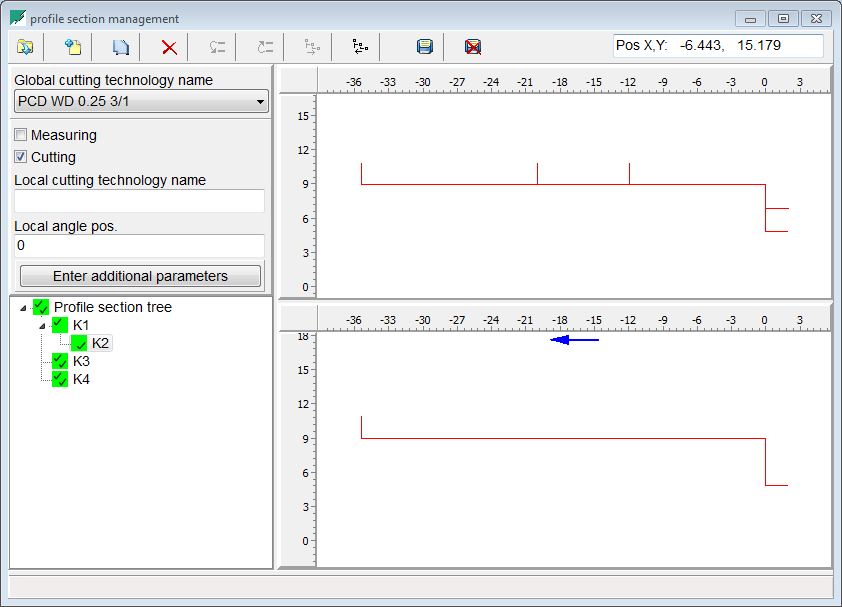
Selektieren der Schneidgeometrie
Einfaches einfangen der Schneidgeometrie aus der importierten DXF-Datei
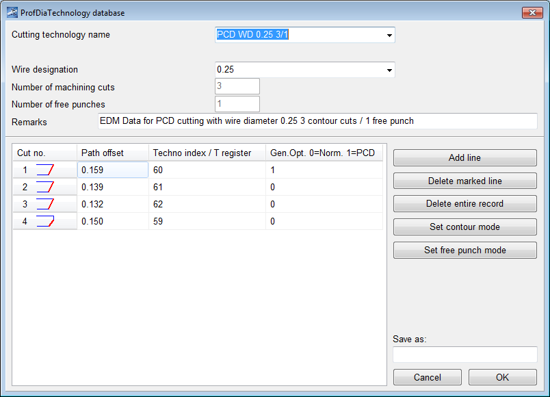
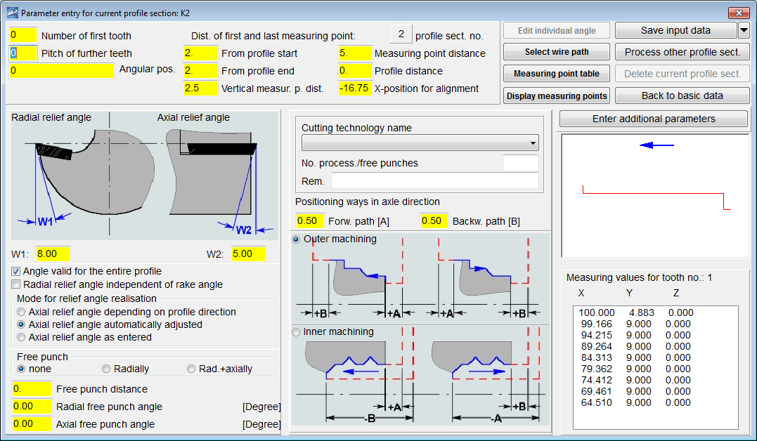
Definieren der passenden Schneidtechnologien
Einfaches und schnelles anpassen der Schneidtechnologien.
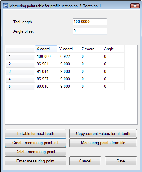
Automatisiertes Einlesen der Messdaten aus der Maschine
Die Schneide wird vor dem Schneiden eingemessem um das Schneidprogramm an die realität anzupassen.
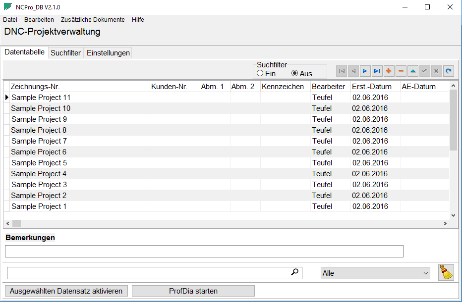
Projektdatenbank
Alle Projekte werden in einer Datenbank gespeichert. Die Datenbank kann auch auf einem Server verwaltet werden.
Moderne 3-D Simulation
Die programmierten Schneidkonturen können hier überprüft werden.

Analyse aller Zähne
Das komplette Werkzeug kann visualisiert und analysiert werden. Bei der alternativ auswählbaren 2D Simulation kann nur ein Zahn sinnvoll dargestellt werden.
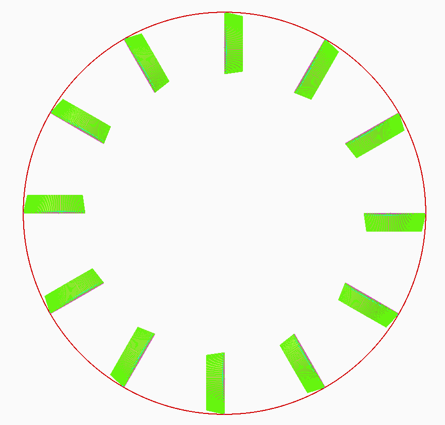
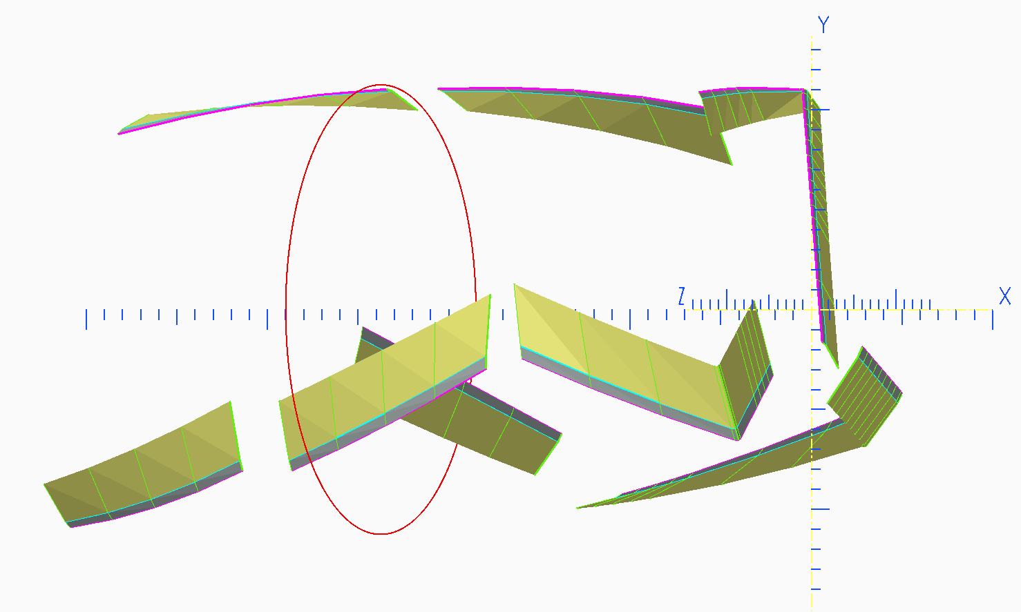
Mehr Möglichkeiten, die Span- und Freiwinkel aller Zähne eines Werkzeuges zu analysieren
Visuelle Prüfung der Freiwinkel, ob das Werkzeug frei läuft. Der optional einblendbare Kontrollkreis kann im Durchmesser, sowie in der Lage entlang der X Achse frei angepasst werden.
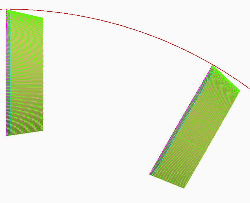
Mehr Möglichkeiten, die Span- und Freiwinkel aller Zähne eines Werkzeuges zu analysieren
Durch stufenloses Zoomen kann die Schneidgeometrie detailiert analysiert werden.
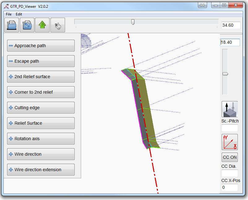
Mehr Möglichkeiten, die Span- und Freiwinkel aller Zähne eines Werkzeuges zu analysieren
Die Schneidengeometrie kann nach dem Einmessen in der tatsächlichen Lage (inkl. Achs- & Spanwinkel) detailliert begutachtet werden. Dies ermöglicht die frühzeitige Erkennung von Messfehlern oder potenziellen Kolissionen.
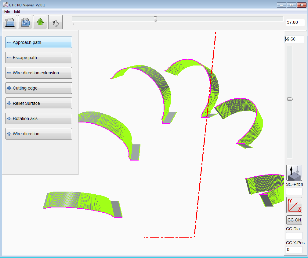
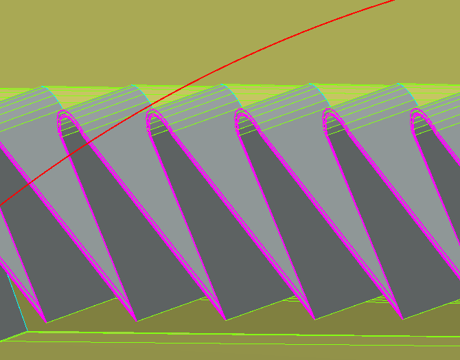
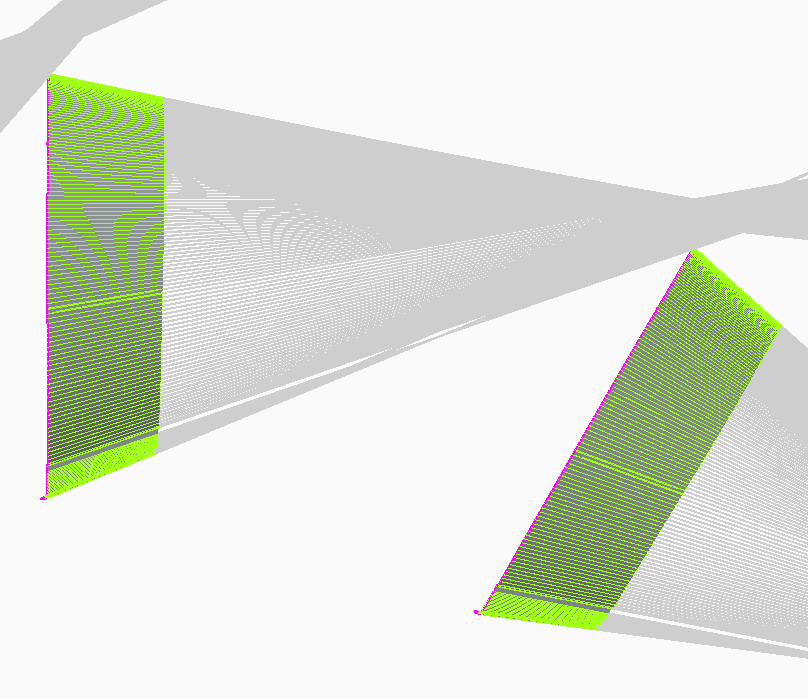
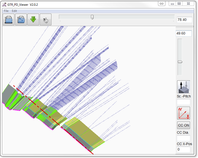
Kollisionsprüfung anhand "Drahtrichtungsverlängerungen"
Diese einblendbare Ebene vereinfacht die visuelle Kollisionsprüfung bei komplexen Werkzeugen. So lässt sich die Notwendigkeit von „Dry Runs" deutlich reduzieren. Die "Drahtrichtungsverlängerungen" können wahlweise in beide Richtungen dargestellt werden.
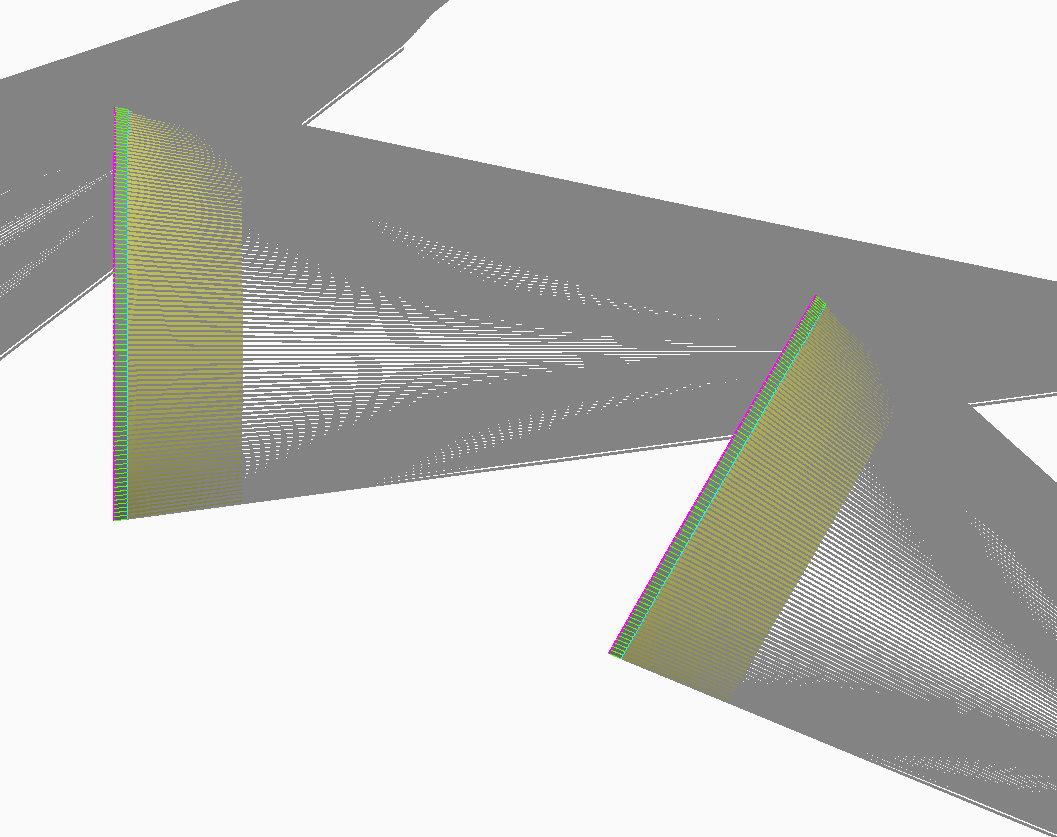
Kollisionsprüfung anhand "Drahtrichtungsverlängerungen"
Hier kollidiert der Draht mit dem Folgezahn. Das Werkzeug wird zerstört.
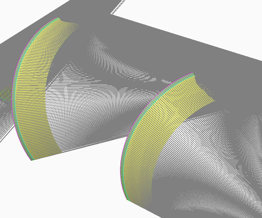
Kollisionsprüfung anhand "Drahtrichtungsverlängerungen"
Durch Optimierung der Freiwinkel sowie An- und Abfahrwege in ProfDia kann eine Kollision mit dem Folgezahn vermieden werden. Die Simulation unterstützt bei der Anpassung und visualisiert das Ergebnis.
Überlagertes Koordinatensystem
Optional kann das Koordinatensystem dargestellt werden. Dies ermöglicht eine einfache Kontrolle der Werkzeuggeometrie.
Einfacher Datenexport
Exportieren der Freiflächen in eine STL Datei zur Überlagerung der Originalzeichnung in der CAD Anwendung.
Optimiert für Touch Displays
Unterstützung von Touch Gesten für Zoom und Rotation des Werkzeugs.
Komplexes Werkzeug für Innen- und Außenbearbeitung
Alle Schneidkanten werden in einem ProfDia Projekt programmiert. Die Gesamtkontur wird aufgeteilt in 3 Teilkonturen.
Werkzeug mit drei spiralig angeordneten Schneidenreihen
Lediglich eine 2D-DXF Kontur wird benötigt. Das Messprogramm ermittelt automatisch die spiralige Schneidenanordnung.
Radiusfräser R=6 Z=12
Fräser mit beliebig vielen Zähnen sind programmierbar. Freiwinkel können beliebig angepasst werden. Nur eine Kontur muss programmiert werden und diese wird mit der angabe der Zähne auf die errechneten Winkelpositoinen verfielfacht.
Profilwerkzeug hergestellt per Drahterosion aus zylindirschen Rohteil
Die Bearbeitungsoperationen sind in einem ProfDia Projekt in fünf Teilkonturen definiert, welche ohne Unterbrechung nacheinander ausgeführt werden. Bei dieser Bearbeitung ist kein Einmessen der Spanflächen notwendig, da die Spanflächen mit definierter Lage innerhalb des Programmablaufs hergestellt werden. Damit kann die Lage der Spanflächen vorab in manuell erstellten Messpunktlisten definiert werden.
Die Profilierung der Werkzeugschneiden von PKD-, CBN- oder hartmetallbestückten Werkzeugen wird in vielen Fällen mittels Drahterosion durchgeführt. Um eine reproduzierbare Genauigkeit des Fertigungsergebnisses zu gewährleisten muss bei der Erstellung der NC-Programme für die Profilierung die exakte Raumlage der Schneidplatten-Oberflächen (Spanflächen) bekannt sein. Da die Lage bei der Vorfertigung in der Regel nicht mit ausreichender Präzision bestimmt werden kann, ist es notwendig die Plattenlage vor der Erstellung des NC-Programms durch einen Messvorgang zu bestimmen. Diese Operation wird von Standard CAD-CAM Systemen nicht unterstützt.
Die GTR Software ProfDia® und ProfDiaF® ist dagegen in der Lage für entsprechend ausgerüstete Maschinen das erforderliche Messprogramm zu erstellen, die ermittelten Messdaten einzulesen und mit diesen Messdaten ein exakt angepasstes Schneidprogramm zu generieren. ProfDia® und ProfDiaF® unterscheiden sich im wesentlichen darin, dass ProfDia® für rotierende Werkzeuge und ProfDiaF ® für feststehende Werkzeuge optimiert ist. Momentan wird das Postprocessing für FANUC, Mitsubishi und Sodick Maschinen unterstützt.
Folgende Merkmale der ProfDia® Programmieroberfläche erlauben eine einfache und intuitive Programmerstellung ohne spezielle Programmierkenntnisse:
- Konturübernahme im DXF-Format aus einem beliebigen CAD-System
- Parametereingabe in spezialisierte, selbsterklärende Eingabemasken
- Gesamtkontur in eine beliebige Anzahl von Teilkonturen mit individuellen Parametern aufteilbar
- Freiwinkel individuell einstellbar für jedes einzelne Konturelement
- Graphische Simulation von Mess- und Schneidprogramm unterstützt die Erstellung fehlerfreier Programme
- Einfache Handhabung durch optimierte Funktionen für den Programm- und Messdatentransfer zwischen Programmierrechner und Maschine
- Gesamter Produktionszyklus voll automatisierbar